Injection Mould Construction

A molding according to the function of each of its parts can be divided into four sections 1. Introductory part of the plastic nozzle into the cavity cavity 2. penunjuang system (support system) 3. demolding system 4. heat transfer system

Mold Base Standard Part

In the manufacture of injection mold, mold base is an integral part, mold maker can make your own mold base or buy a standard mold base, the system of the mold base can be adjusted with the construction standards required, both for the two plate and three plate, stripper plate ejectors, hot runner and mold base for a screw, when the entire standard mold base is not there to meet the new final step is to make a special mold base.

Injection Mould Classification

classification or types of mold injection very depend on what we need to make the plastic parts, because every parts have specific and unique design. when design molds we must see what the influencing factor like geometry, number of cavities, ejection principle, plastic material and shape of part.

Injection Mold Cooling

This section is the most important part of the overall mold cylcle time, because in one cycle time, the process of heat exchange to spend about 70-80% of the total cycle time, thus setting the optimal heat transfer system will greatly affect the quality and cycle time of a product.

Undercut System : Cam, Angular, Lift Cavity, Loose core

cavity and core, and its derivatives when there are undercut on product, design and construction of a good core cavity and in accordance with the requirement could increase the life of tooling itself, reduce material consumption, reduce dependence on maintenance inserts, and can reduce the cost of making the mold so the mold cost per products also declined.

Friday, December 21, 2007

Construction Injection Molds Classification

classification or types of mold injection very depend on what we need to make the plastic parts, because every parts have specific and unique design. when design molds we must see what the influencing factor like geometry, number of cavities, ejection principle, plastic material and shape of parts.

The basic classification of mold based on construction shown on picture below


1. Standard Molds
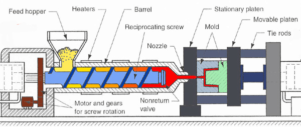
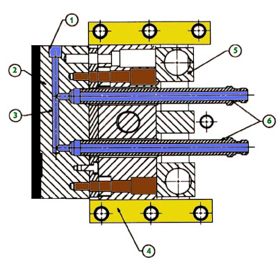
the standard mold is the most simple design, basically the standard molds is same as two plate molds construction, they divided in two side : cavity side and core side, cavity side is the side that construct to flowing plastic material from nozzle to cavity parts, basically they consist of sprue, runner.

core side construct to make shape for core, demolding system and ejection system, at this side we design ejection system.
standard mold have one parting line, and have one opening direction. this type of mold use in all kinds of plastic parts that doesn't have undercut, inner and outer screw.
Light brown color little and straight in ejection system is shown ejector pin.


2. Slide mold

development from this mold type is the used slider parts in various molds types, basic slide mold is transfer horizontal movement of mold to vertical movement, this types of molds is used to make parts with undercut, you should see more at the post when we need slider for learn more.


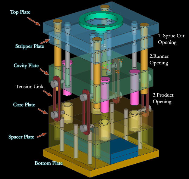
3. Three plate molds
basically three plate molds has two parting line, and floating plate, floating plate support by support pin, Since the mold has two parting planes, the runner system can be located on one side of floating plate or make special plate that attach in floating plate, we called runner plate, see post about runner plate. Three plate molds are used because of their flexibility in gating location. this types of molds is flexible even use in multiple cavity.

note : floating plate also called cavity plate or plate number 3, to know more the different between two plate mold and three plate mold see the posting about Basic and Types Molds Construction

4. Split Cavity Mold
basically the split cavity is same as 2 plate standard mold, but the cavity have split block to make undercut product or external threads.


this type of mold use when the slider is not enough to make the undercut or the threads. the disadvantages of this mold is when use for little parts, the construction will difficult.


5. Mold With Screw Device

this mold special to make thread forming, the core can be rotate when demolding process, both internal or external threads can be forming by this type mold.


from those picture we can see that they have gear device, the gear will rotate when form thread.


6. Stripper Ejector Mold
this type of mold have special purpose to make a cup shape without undercut, stripper ejector will make ejection more easy, same movement and power at the product and without a lot of marks in product


Molds with complex and difficult design can be integrated or combined one to the others mold type.

Saturday, December 15, 2007

Introduction to Mold Engineering of Thermoplastic

most electrical, and home appliances made from plastic, one of technology to make plastic product is using mold, specially injection mold of thermoplastic, basically when thermoplastic material heated, they will change of state, thermoplastic material will become soft, melt and flowable, when cooled again, they become solid again.

What is Injection Mold ?

there are some definition of injection mold

is a manufacturing technique for making parts from both thermoplastic and thermosetting plastic materials in production (wikipedia.com)

A manufacturing process for forming objects, as of plastic or metal, by heating the molding material to a fluid state and injecting it into a mold.(www.answer.com)

Herbert Ress, 2002 : an injection mold is arrangement, in one assembly a number of cavity spaces built to shape of the desired product, with the purpose of producing plastic parts in large number

this blog define injection mold is manufacturing process to make plastic product that have cavity spaces to shape the product by heating and injection pressure.

Types of Injection Molds
based on how injection mold would be processed wikipedia.org devide injection mold as 7 types until now, they are
1. Reaction injection molding
2. Liquid injection molding
3. Gas assist injection molding
4. Co-injection molding
5. 2-Shot Injection Molding
6. Fusible core injection molding
7. Rapid injection molding

based on type of opening method and runner system, The DIN ISO standard 12165, "Components for Compression, Injection, and Compression-Injection Molds" classifies molds on the basis of the following criteria:
1. standard molds (two-plate molds)
2. split-cavity molds (split-follower molds) stripper plate molds
3. three-plate molds
4. stack molds
5. hot runner molds

depending on material to be injected classifies as :
1.thermoplastic injection molds
2.elastomer molds
3.thermoset molds
4.structural foam molds

picture below shown 3 plate mold type with cold runner system and ejection system
click the picture to enlarge


closed Condition
picture below shown 3 Plate Molds Types in 3D design, in closed position with support pin, puller bolts, leader pin or positioning pin.


you can also learn more about basic pin construction at post about pin in molds
Opening Condition
then the construction molds of 3 plate type when opening is like picture below

picture below is shown three plate condition when open


we also can learning more about ppening Sequence, why and how the molds open, and explaining each molds opening step or sequence at post about opening construction

those opening sequence is just for 3 plate type, 2 plate type is more easy becouse just have one opening parting line.

Thursday, November 22, 2007

Top Plate, Stripper Plate,Sprue Bush and Runner Lock Pin Design

at the picture below you will see a set of Top plate until stripper plate design related with runner flow, at this picture support pin exclude. the mold type in this picture is 3 plate type.

the runner system accommodates the molten plastic material that coming from barrel, and guide it into mold cavity, the dimension, configuration, shape, and system connection with mold cavity will affect filling process.


as see from that picture, red plate indicate isolated plate, it's doesn't matter you use isolated plate or not, but you must see more in injection machine, if it needed isolated plate give it. number 1 and 2 in black plate it's indicated top plate for number 1 and stripper plate for number 2, those picture shown 3 open mold type.
after injection, in ejection process stripper plate will open because puller bolt pull it( not include at those picture).

runner ejector set will needed to push runner, after ejection, but if you use arm robot or manual take the runner by hand operator it doesn't needed. runner ejector set always contains spring, those spring will push pin in ejector set and will push the runner.

runner lock pin function is to pull runner when ejection begin still in top plate, if runner adhere in stripper plate, the robots or operator will difficult to take the runner, because no ejection system for runner in stripper plate.

when design the runner system and ejection system for runner in 3 plate type of mold you should use those mold accessories.

Monday, November 19, 2007

Types of Runner depending temperature

there are various concept and type of runner, here we will give explain about runner type depending on the temperature control, we could divide in 3 type :
1. Standard runner system
2. Cold runner system
3. Hot runner system

standard runner system are directly machined into the mold plates (plates 2 or plate 3) but we can also make in special plate that called runner plate, this plate usually use in 3 plate mold type and attached in plate three(cavity plate)
at this picture below shown that runner directly machined in plate three


but picture below shown special plate called runner plate, those runner plate will attached in plate three, you can see from this plate that mold will have 4 cavity od product.


Cold runner system
this runner system have similar use with hot runner, but in different temperature, the temperature between 80-120 C, this Cold runner system used in reactive material such us rubber and thermosets type of plastic.
the difficulties in Cold runner system is
- high pressure consumption, so design more expensive
- because material is reactive, a little different temperature make different viscosities, this will make every cavity have different time to full fill.

Hot Runner System
this system should be viewed as extended nozzle in form of block, the hot runner system contains : sprue bush, runners, gate and extended nozzle, the advantage of hot runner is
- they can completely eliminate runner scrap, so there are no runners to sort from the parts,
- no runners to throw away or regrind and remix into the original material.
- no loss of melt and thus less energy and work input
- easier for fully automatic operation
- very good quality because melt can be transfered into the cavity at the optimum site

the disadvantages are :
- high cost
- thermal isolation from the hot runner manifold block is problematic

Hot runners are popular in high production parts, especially with a lot of cavities

there is 3 type of Hot Runner are :
1. the insulated hot runner,
Insulated runner molds have oversized passages formed in the mold plate
Heated type Hot runner
2. the internally heated hot-runner system,
3. the externally heated hot-runner system
internally heated and externally heated. The first is characterized by internally heated, with the heat being furnished by a probe and torpedo located in the passages. This system takes advantage of the insulating effect of the plastic melt to reduce heat transfer (loss) to the rest of the mold. The second consists of a cartridge-heated manifold with interior flow passages, look at picture below to learn more

this picture take from http://www.scudc.scu.edu

Sunday, November 18, 2007

When we need slider parts in Mold Design

second previous post i have post about the slider parts and construction in complete mold base , then now i give a little brief when we need slider in mold design, basically we design mold from our customer, first is we must look the parts that we will make by plastic mold, look mare at the drawing so we can know about tolerance and critical point of parts, seconds is define the parting line, first parting line is between core and cavity parts, and after that if the parts have side form we must define slider parting line, look picture below


from those parts we know that we need slider parts, side hole and other shape that can not form by core and cavity became slider parts. below is picture in 3D modeling,look at the hole shape in side, those shape need slider part.


and how the construction of slider, more about construction mold you can see by clicking mold construction or molds parts in quick topic, basically here i give slider 3D modeling and parts name, those parts names i take from Misumi standard mold design


you can use this tutorial for education and others purpose but still write copyright from this site.

Monday, November 12, 2007

Mold Handling Picture after Assembly

Picture below show 3 plate mold after assembly, the position indicate ready to handling by crane, eye bolt was attached at center of mold plate.

after assembly process, make sure you has attached the tension link in 3 plate mold type or safety bolt or magnet in 2 plate type of mold this to prevent mold plate falling down when handling up with crane, when design eye bolt for handling, give bolt hole about 1 cm more to cavity direction from center line of mass of mold, it's commonly in plate 3 or 4 depending on how wide each mold plate, why it's must move about 1 cm ? the reason is same as safety bold, by move those bolt position when handling with crane mold base will decline about 5-30 degree, and top plate in upper position, this method make more secure when handling.

at this picture below, number 1 is eye bolt position in ready position to handling, and tension link (2) was attached.


from where we know that those mold is three plate, from the characteristics of three PLATE MOLD we can see from picture that :
1. Attached tension link, tension link function is o pull plate number 3 or cavity plate then by puller bolt, cavity plate will also pull the second plate, and cut the runner from nozzle.
2. second plate, it's indicate that those mold is 3 plate mold type, why because in 2 plate type, second plate is doesn't use. second plate is necessary when gate type is pin point gate.
3. runner plate, if you see more carefully, between second plate and third plate attached runner plate, in 2 plate mold type, runner plate does not use, because runner attached in third plate.

green arrow show injection nozzle machine where must be attached and indicate flow of plastic material during injection process.


Sunday, November 11, 2007

Slider Design and Basic Construction

picture below show slider basic construction in Mold, various construction and litle part available in slider but the basic construction of slider is same, look picture below, sorry if this picture is too grainy, i'll make a new one.


the main part from those picture is mold plate, number 1 until 10 is shown the plate of mold
plate 1 is top plate
plate 2 is gate opener plate, retainer plate, and others name depend in fabrics
plate 3 is cavity plate
plate 4 is core plate
plate 5 is backing plate
plate 6 is support plate
plate 7 is ejector plate
plate 8 is ejector retainer plate
plate 9 is bottom plate
plate 10 is runner plate

and the slider part name are
g for angular pin, this pin always have certain degree, usually between 10-30, angular pin will transfer vertical movement to horizontal movement, others construction, angular pin not from the top but from bottom, this kind of construction is rare to use now.
h is slider core, when contact with angular pin, this part also the core from slider construction, at this part we can attach insert part that mold the shape of plastic.
i is slider locking block, we can depend in angular pin when mold closed, slider pin is too week, so the holder of pressure from inside mold during injection process is locking block.
k is slider lock plate, for non mass production you do not have to attach this part, but if the mold used in mass production, i suggest to use this part, because slider locking block and slider core always have friction, then when this part broken or got abrasive is will need expensive cost to repair it, so use lock plate is better, is cheaper.
l(L) is slider insert, this part which form the plastic product, it's attach in slider core

Saturday, September 15, 2007

Coring uniform wall thickness

when design a mold then we find nonuniform wall thickness, we can make little graduation translation using core, of course if there was not function parts,
ordinary parts like not cosmetic parts, touching with others parts, sliding and etc, should we change by making insert in core or cavity side. look at picture below
when a parts have no uniform thickness after injection process, sink marks and unfill product like void will occurs,


Different wall thicknesses in the same component cause differential shrinkage which, depending on component rigidity, can lead to serious warpage and dimensional accuracy problems To attain uniform wall thickness, thick-walled areas of the moulding should be cored like picture above,
the best core for graduation translation and easier material flow is by make radius in every corner, beside flow more easier there will easy when machining process used,and no need EDM process so it's should cost down the price of product.

Friday, September 14, 2007

Wall Thickness Design - Maksimum

Dependent on the part design and size, typically, for injection molded parts, the wall thickness will be in the range 0.5 mm to 4 mm (0.02 - 0.16 inch).
For parts made from most thermoplastics, nominal wall thickness should not exceed 4.0 mm. Walls thicker than 4.0 mm it is will increase time required for cooling and will result in increased cycle times

Changing the wall thickness of a component has a significant effect on the following key properties:

1.component weight
2.achievable of cycle time because more time 3.for cooling and injection
4.tolerances of product
5.achievable flow lengths in the mould
6.production cycle time of the component
7.rigidity of the moulded part
8.quality of the component in terms of surface finish, warpage and voids.
9. will affect to determines mechanical properties

What the Disadvantage when Thickness not Uniform

In the design of plastics components, it is important to aim for uniform wall thickness. Different wall thicknesses in the same component cause differential shrinkage which, depending on component rigidity, can lead to serious warpage and dimensional accuracy problems

what we should do when design a mold that have different thickness, look at the following picture, we should make as possible uniform or make the transition of product is gradual


Generally, the maximum wall thickness used should not exceed 4 mm. Thicker walls increase material consumption, more need time for cycle time considerably, and cause high internal stresses, sink marks and voids, look at picture below


Thursday, September 13, 2007

Wall thickness in mold design


when design a product The basic wall of the part of the melt during injection, should be kept uniform, this important to prevent sink after injection.
even we use cooling after injection part well deform because shrinkage, at this time if wall thickness does not same part will warpage stress

they key is keep wall thickness part as uniform as posible

Monday, September 10, 2007

SPRUE BUSH and LOCATING RING

when you choose sprue bush, make sure you was know the diameter ball nozzle of plastics injection (SR) is less than diameter ball (SR - at picture below indicate by R)

if diameter R of Sprue bush to little than nozzle SR diameter, that will not good match or touching, if injection machine working plastic flash will out between nozzle and sprue

LOCATING RING

some mold designer usually use Locating ring to prevent unmatching nozzle of injection machine, before choose inside diameter of locating ring, we must know the outer diameter of nozzle that will touch with locating ring, at the picture below written in purple

Red color indicating flow of plastic material, from this picture we can take a conclusion that the picture is 2plate type of mold, look at picture there is no runner plate, and the gate type is side gate


Z pin Ejector

is used to make the runner ( RED COLOR) still adhere in core side when mold open and take the product, then Z pin will push the runner together with other ejectors

Saturday, September 8, 2007

Runner System and Construction

picture below show a simple runner system in mold construction, begin from nozzle until gate, nozzle for mold usually located in plate 1, plate 1 is upper plate,
when you design a runner system, basically like picture below, you must know location of product, is important when we decide where gate to be placed, here is the basic rule :
1. Look at drawing and 3D CAD data from the product, make sure you was choose where is cavity side and where is core side, give attention for tolerance of product
2. Do not locate gate in the precision tolerance, if is must to make a little grove in the product when you choose pin point gate type, Picture below use pin point gate type.
3. make sure the flow will steady for all side


Sunday, August 26, 2007

Mold Timing and Terminology

Dry-cycle: The total time required for the (machine) clamp to close and open, or the sum of the mold opening and the mold closing time. Today’s fast machines have dry-cycles in the order of 1–3 seconds. A short dry-cycle is of particular importance with fast-cycling molds. The dry-cycle also depends on the length of the clamp stroke.
Opening time: Usually quite fast. The ejection preferably should take place during this time,to reduce (or to omit completely) any mold open time. Occasionally, mold opening speed may need to be slowed down to suit the ejection method.
Closing time: Usually quite fast, except for the final approach before the mold is fully clamped up, to permit the mold protection system to operate in time before serious damage is caused to the mold.
Mold protection: A system which senses (at the moment of final closing the mold) whether there is foreign material (dirt, plastic pieces, products which failed to eject, etc.) between the mold halves which could cause damage to the mold. A signal from the mold protection system will cause the mold closing to stop before damage occurs and sound an alarm. It usually automatically reopens the clamp so the foreign material can be removed.
There are many types of mold protection systems, such as electric, optical, or pressure activated. Some are more sensitive than others and may not always save a mold from damage.
Mold open (MO) time: This is lost time. This time should be as little as possible. It can be zero.
Mold closed (MC) time: Time from the moment the mold has closed until it reopens. It is the
sum of the following times: Injection time: the time to fill the mold with plastic (usually with high injection pressure).
Hold time: the plastic in the cavities is held under pressure usually lower than the injection pressure to add plastic volume as the plastic shrinks within the cavity.
Cooling time: the time from the moment the injection (or hold) pressure is off until the mold starts opening. (This term is actually a misnomer, since the cooling is always on and starts to remove heat from the plastic as soon as the plastic enters the mold.)
Ejection time: the time required to eject the products from the molding area so that the mold can re-close without catching an ejected piece. Preferably, this should take place during the opening time so as to eliminate the need for additional MO time. In some molds, it is not possible or practical to eject during the mold opening, and the ejection takes place
partly or solely during the MO time.

conclusion
Dry-cycle- Total Time required for the clamp to close and open (sum of mold opening and closing time).
Opening Time- Time it takes to open mold and usually eject part
Closing Time- Time it takes to close mold
Mold Protection- Halts molding operation if a foreign material (dirt, flash, debris) is detected in mold cavity
Mold Open- Time the mold is actually open
Mold Closed- Time the mold is closed and usually includes
o Injection Time, Hold Time, Cooling Time
Ejection Time- Time is takes to eject parts and is a part of Mold Open Time

Thursday, March 8, 2007

Assembly Inspection New Mold

Pre-Assembly Inspection
for a New or Reworked Mold
there are following important point to check list when assembly a new or reworked mold, following pinture below show three plate mold when all parting line open


• Check all shutoff areas with spotting blue. Tryout any pieces to be insert molded in assembly, check fit and shutoff
• The cavity & core blocks have 0.002 preload per side (above the mold base plates)
• Cavity surface finish is correct to print. As a rule remove all tool and EDM marks, especially deep ribs.
• Check for nicks, scratches, damaged edges or corners, chipped or damaged pins and damaged or loose pin holes.
• All cavities have been numbered, and have part numbers (if applicable)
• All inserts are numbered to correspond to cavity numbers. Details should be stamped with detail number and material type
• Tool has pry slots (on back side of "A", both sides of "B", & top of "Ejector" plate) and is chamfered in correct areas
• Water line countersink diameter is correct for Jiffy-Tite plug being used. Check plug holes for smoothness, lead in chamfer, & cleanliness. Sealant has been used on all threads. Jiffy plugs, regular plugs, baffles, and bubblers are in place and have been flow and pressure tested.
• Mold Info has been stamped correctly on the Support plate, all water lines are clearly stamped, and stamp "top of mold" and "operator side" on the appropriate sides
• Verify that all cavities have gates and the gates are the same size.
• All sliding parts must have grease grooves, be lubricated, and move easily.
• Verify that slides do not interfere with ejector pins or other moving components. Verify that travel is sufficient to clear molded part
• Check for proper clearance on angle pins, and slides when entering opposite side. Make sure pins don't bottom out. Check if slides lock properly in slide retainer.
• All limit switches must be orientated properly for wiring and function.
• Check hydraulic cylinders for length of stroke.
• K.O. holes are in correct location and tapped to correct dimensions (if applicable).
• Verify that all pins, sleeves and lift cores have the proper hole clearance, head clearance and proper depth clearance. All pins and sleeves must have lead in clearance and lead in chamfer in core insert. Must be a smooth transition.
• All return and ejector pins, and support pillars are the correct length, ejector system moves easily, all pins are in place (and should be marked for proper location), and the entire assembly lubricated
• Push ejector plate forward and check if all pins, sleeves, lift cores and all other moving components spin freely. Wiggle to verify correct clearance and that all components move freely
• Check that ejector plate can use the full length of travel and has spring return if needed. Check if runner & part will clear the core
• Verify that sprue puller design will work as needed
• Open and close tool in assembly to check for any interference. Activate any and all side actions and lifters to check for proper travel and interference of any kind
• All core pins are the correct length, and all pins are in place, do the necessary pins shutoff?
• Runner must be benched smooth with rounded corners and transitions. Gate to Runner transition should be blended smooth. (Parting Line edges stay sharp)
• All runners are vented at every direction change, and part detail is vented directly opposite the gate, at the parts ends & corners, and every 2 inches in between as necessary. Vent all guide pins
• Verify that all plates have eyebolt holes on every side
• Safety strap is attached to mold between A and B halves on the operator side
• Locating ring and sprue bushing are in place, and sprue radius and orifice diameter is correct size. Sprue Busing is rotation locked and retained
• Clamp slots are in place and free from any interference.
• If inserts are fit on surface plate, check fit in assembly also.
• Demagnetize all components.
• All screws/bolts are in place and tight. (Follow a pattern to prevent missing a screw)
• Verify that cavity, core, slides, mold base and all other applicable parts are clean and clear of chips, debris, and benching grit, and spotting blue, especially deep ribs and bosses.
• Check all holes for missing pins by looking in every hole of the assembled mold.
• Verify that parting line locks function properly.
• Open and close mold on bench that everything functions properly. Check if slides clear ejector pins, lift cores and any other moving parts with sufficient clearance and that mold closes freely.
• On hot sprue bushing, check if it is properly installed and assembled, make sure all components are installed and no wires are broken or damaged. Check that wire channel is in mold base and that clamps are in place to hold wires.
• Water lines must be pressure tested with diversion plugs, "O" rings and correct jiffy-plugs installed
• All slides, core pins, angle pins, cam locks and guide pins must be greased.
• For Hot Runner molds check the size and fit of every drop diameter. Check overall lengths and heights to verify heat expansion and proper "crush".
• For Hot Runner molds check that all wiring is in a channel, free from damage, and free from possible "pinches" during assembly. Check continuity all all circuits (compare all zones to the drawing, note any changes or additions)
• For Three-Plate molds, verify that all latches function properly, that they latch and release in assembly, and that plate separation is sufficient to let both the part AND the runner drop through. Also check that all latch dowel pins are secured so as not to come loose during operation.
• Tool is sprayed with WD-40 or equivalent for shipping

Assembly and Disassembly Mold

The following is a good checklist for disassembly and assembly of a plastic injection mold. Some of our customers to not have trained moldmakers on staff to perform this kind of assembly and disassembly so we have listed a procedure here to help give your tooling room staff a good start, HOWEVER, this must be done at your own risk! We HIGHLY recomend that every molding facility should have skilled moldmaking professionals on staff to perform assemblies, disassemblies, maintenance, and repairs.


the picture at the top show disassembly various parts of mold
Disassembly:
• The mold must be placed on two rails on a clean table with sufficient space. Tools used must be in good condition and should include allen wrenches, aluminum prybars, rubber mallet, duct tape, and some containers.
• Separate mold at parting line carefully and look for any visible damage. If mold is damaged, report it at once. Check for rust in core and cavity and report it at once if found.
• Have containers to put all the parts in and identify it with the proper job number.
• Check for core pins in Ejector Housing (at the bottom clamp plate) and remove the core pins first.
• Remove all necessary screws in the Ejector Housing and remove it.
• Remove screws from the Ejector Plate and remove it.
• Check if all pins are marked, if not mark as necessary.
• Check if lift cores are marked, if not mark as necessary.
• Remove all pins and parts from Ejector Housing. Protect all fragile parts and critical areas with duct tape.
• Remove all water line jiffy-plugs
• Remove all slides assemblies and protect all critical areas with tape or carefully store in container.
• Remove the Sprue bushing, hot sprue, or any hot runner system.
• Remove all screws from cavity and core inserts and install two or four longer screws in cavity and core. Then knock out cavity and core inserts from mold base by hitting screws with a rubber, aluminum, or copper mallet. BE CAREFUL NOT to knock insert out onto the bench or floor and damage it. If you can't bump the insert out into your own hand GET HELP.
• Once the primary inserts are removed, remove all sub-inserts, gate inserts, core pins, etc. and protect all critical edges with tape or carefully store in container.
• Carefully clean all details with a clean, mild solvent and clean towels being careful NOT to damage sharp edges, parting surfaces, shutoffs, or the cavity finish.
• Finally, store all inserts in such a way that the molding surfaces are protected and cannot be accidentally damaged.


Finishing Assembly Picture
Assembly:
• Have all the mold plates, inserts, and components in one place ready for assembly. Have a clean table and two rails to slide plates on. Tools used must be in good condition and should include allen wrenches, aluminum prybars, rubber/copper/aluminum mallets.
• Cleanliness is critical in mold assembly. Make sure all plates, inserts, and components are clean and free from grit, debris, and chips. After you have carefully cleaned all details with a clean, mild solvent and clean towels THEN wipe everything again with your clean, bare hand to remove small grit (Careful NOT to damage sharp edges, parting surfaces, shutoffs, or the cavity finish)
• Install all sub-inserts, gate inserts, core pins, etc. into the primary inserts. Check that all inserts and pins are marked and that they are installed in the correct location and position.
• Mount the B-Plate to the Support Plate
• Install the B-Half insert set, any slide assemblies, and any other B-plate components. Check that all parts are marked and that they are installed in the correct location and position.
• Insert and grease all ejector pins, ejector sleeves, and ejector blades through the pin retainer plate, support plate, and core inserts. Install all return pins and springs. Install and grease any Lifter mechanisms. Bolt on the Ejector plate.
• Assemble the ejector housing, with support pillars, guided ejection pins, etc. Guide this assembly through the ejector & other plates and bolt it to the support plate. Insert any core pins that mount in the bottom clamp plate and fasten their backup plates. Lubricate the entire assembly.
• Verify that the Slide assembly moves freely, is greased, and that the slide retainer is functioning properly.
• Move the Ejector assembly forward and check if all pins, sleeves, lift cores and all other moving components spin freely. Wiggle to verify correct clearance and that all components move freely
• Check that ejector plate can use the full length of travel. Check if runner & part will clear the core when ejected.
• Mount the A-Plate to the top clamp plate
• Install A-Half insert set, heel blocks, angle pins, and any other A-plate components. Check that all parts are marked and that they are installed in the correct location and position.
• Install the locating ring & sprue bushing, check that sprue radius, and oriface are the correct size and verify that the sprue bushing is rotation locked and retained
• If the mold features 3-plate or hot runner system install them at this stage.
• For Three-Plate molds, verify that all latches function properly, that they latch and release in assembly, and that plate separation is sufficient to let both the part AND the runner drop through. Also check that all latch dowel pins are secured so as not to come loose during operation. Lubricate the whole assembly and verify that it moves freely.
• For Hot Runner molds check that all wiring is in a channel, free from damage, and free from possible "pinches" during assembly. Check continuity all all circuits
• Install all jiffy-connectors with teflon tape or suitable thread sealant and water test.
• Check all limit switches
• Spray with WD-40 and close the assembly
• Verify that the mold has a mold strap and that it is fastened correctly

Wednesday, March 7, 2007

Hot runner construction and method

Hot runner is a method in plastic injection molding with a mold suitable for use insimultaneous molding of a large number of articles at a time by hot-runner molding technique. The mold has a hot-runner block in which disposed are a plurality of gates through which the molten resin is delivered to the molding cavities formed in a cavity block which is usually kept at a low temperature. The gate area of the hot-runner block is kept in contact with the cavity block, for the safe deliver of the resin to the molding cavities, in the injection step and, therefore, is cooled by the cavity block. Consequently, when the injection is completed, the gate area has been cooled to such a low temperature as to cause a solidification of the resin in the gate area. The hot-runner block is then separated from the cavity block and brought into contact with a hot gate-temperature recovering block, so that the gates are heated to remelt the solidified resin, before the next batch of injection is performed, so as to recover the fluidity of the resin

Types of hot runner systems
There are two types of hot runner systems:

Insulated runners
Insulated runner molds have oversized passages formed in the mold plate. The passages are of sufficient size that, under conditions of operation, the insulated effect of the plastic (frozen on the runner wall) combined with the heat applied with each shot maintains an open, molten flow path.

Heated runners
For heated runner systems, there are two designs: internally heated and externally heated. The first is characterized by internally heated, annulus flow passages, with the heat being furnished by a probe and torpedo located in the passages. This system takes advantage of the insulating effect of the plastic melt to reduce heat transfer (loss) to the rest of the mold. The second consists of a cartridge-heated manifold with interior flow passages. The manifold is designed with various insulating features to separate it from the rest of the mold, thus reducing heat transfer (loss).


hot runner system picture

One of the more important enhancements you can incorporate into your mold to improve molded part quality, reduce production times, and remain price competitive is to equip it with a quality hot runner system. A hot runner-equipped mold can :

• Materials cost savings - no runner to regrind or reprocess
Least expensive cost / piece
Reduction of energy costs
Shorter, faster cycle times - no runners to cool
• Smaller machines - reduced shot volume into runners
Automated processing – runners do not need to be separated from the parts
Gates at the best position for economical design
• No runners to remove or regrind

• Reduces the possibility of contamination
Lower injection pressures
Lower clamping pressure
• Shorter cooling time
Shot size reduced
Cleaner molding process
Eliminates nozzle freeze
Consistent heat within the cavity
There are, however, a few disadvantages to hot runner systems that need to be considered
• Hot runner molds are more complex and expensive to build than cold runner molds
• Higher initial start-up costs than for cold runner systems
• Complex initial setup prior to running the mold
• Risk of thermal damage to sensitive materials
• Elaborate temperature control required
• Higher maintenance costs – more susceptible to:
o Breakdowns
o Leakage
o Heating element failure
o Wear caused by filled materials


other type hot runner system

Lower Cycle Time, Increase Output
The cycle time of any mold is largely influenced by the cooling cycle—how fast the resin can be sufficiently cooled so that the part can be ejected without permanent deformation. In any given mold, the areas that take longest to cool are those with the thickest wall section.
njection time is another component that differs between comparable hot and cold runner equipped molds. The injection time difference will be the extra time required to fill the cold runner.
Close and open stroke of the press is extended with cold runner equipped molds. The travel must be increased to accommodate safe ejection of the cold runner.
Parts molded with hot runners better lend themselves to automated part removal. With no runner to interfere with part removal, secondary mold processing times involving manual labor, including part/runner separation, part trimming and packaging, are reduced or eliminated entirely.
Significantly Reduce Production Costs
Although a more expensive capital investment upfront, a hot runner system is a significantly more cost-efficient means to keep production costs to a minimum over the long run.

Resin Savings
Since there is no cold runner to discard or recycle, resin consumption is reduced. Depending upon the molding application (i.e., medical components or parts requiring FDA approval), the product may require 100 percent virgin material—increasing overall consumption.
Energy Savings
Energy is wasted plasticizing, cooling and regrinding each cold runner that is produced. Increased energy consumption also is a direct result of extended cycle times.
Labor Savings
Secondary operations—such as manual part de-gating and trimming—are eliminated entirely with a hot runner system.
Mold Cost Savings
A smaller cavitation hot runner equipped mold may be able to satisfy production quotas using a smaller number of cavities since it runs at a faster cycle. The smaller mold frame size may enable installation into a smaller press.
Injection Press Costs
Hot runners allow reduced injection pressures during packing, as the system does not have to deal with injecting resin through a cooled runner. Melt in the cold runner may lose heat en route to the gate, possibly requiring higher heats and/or pressures from the injection molding machine. By reducing the injection pressure and clamp tonnage required, it is often possible to run the same part in a smaller tonnage machine as the clamp tonnage required is not as great.


sample heater in hot runner

Benefits for Long-Term
Despite the higher initial cost, the long-term benefits of equipping a mold with a hot runner system can be easily justified. A hot runner-equipped mold can effectively reduce molding costs without significantly increasing the complexity of the mold design. Generally, mold build leadtimes are not impacted as the hot runner is designed and manufactured in parallel with the mold.
It is in the best interests of the moldmaker to continually suggest ways for his/her customer (the molder) to reduce mold operational costs and increase mold output. By demonstrating these initiatives, the moldmaker confirms to the molder that the moldmaker is taking an active role in increasing the molder's overall profitability, which in turn increases the likelihood of repeat business for the moldmaker.

Mold part and construction

Many type of mold in the platic industry but generally mold devide in 3 big section there are :

Two plate mold
Two plate mold basically when opening the product after plastic injection process mold just devide in two parts core side and cavity side, this type molding only have one parting line, product parting line with located between core side and cavity side
Look at picture below for more detail


Three plate mold
Basically when product out after injection process this mold type divide in three parts, beside that, this type mold have three parting line, first between top plate and runner stripper plate, second are between stripper plate and cavity plate, the last is parting line product that located between core and cavity (see picture below)


hot runner mold (runner less mold)
this type basically similar with two plate mold but not same, hot runner mold always heating the runner, so runner will not drop out with product, so it is some times called runner less mold, there is two big parts when opening after injection, core side and cavity side. Look at the picture below


Mold Construction
look at the picture, the parts of mold are


1. Top plate (plate 1)
2. Striper plate (plate 2)
3. Runner plate (plate 10)
4. Cavity plate (plate 3)
5. Core plate (plate 4)
6. Spacer Block (plate 6)
7. Bottom plate (plate 9)
8. Ejector plate (plate 7)
9. Ejector retainer plate (plate 8)

other function from all parts will explain in other post

Monday, March 5, 2007

Polystyrene Injection Process


Polystyrene is one of the best materials for injection moulding. Cycle times with polystyrene are usually short due to ease of melting, fluidity and reasonable set up times. Complex tooling can be used.

The surface finish of the final product is also good, and the low mould shrinkage of polystyrene is a useful factor.
Moreover, due to good inherent thermal stability, polystyrene can easily be recycled.
Finally, polystyrene can be easily compounded or coloured in the melt phase and formulated for specific performance (gloss, anti-static properties,...).

General facts
Total Petrochemicals’s Polystyrene can be processed by every conventional technique used for thermoplastics. The general properties of polystyrene allow for a wide processing window in terms of both temperatures and pressures.

Drying
Polystyrene is not hygroscope, and is delivered in dry pellet form. Drying is not normally necessary. Care must be taken to avoid conditions which can cause condensation, this can lead to the appearance of splash marks on the finished moulding. If necessary, the product can be dried in a ventilated oven for 2 hours at a temperature of about 80°C.

Change of material or colour
All polystyrenes are "compatible", either GPPS or HIPS. The change from one grade to another is straightforward. Polystyrene is not compatible with other polymers such as polyethylene (HDPE or LDPE), PVC (Polyvinyl Chloride), ABS (Acrylonitrile Butadiene Styrene), PMMA (Polymethylmethacrylate), or PA (Polyamides) and, in general, other thermoplastics. This means that the machine has to be purged thoroughly in order to avoid such phenomenon as delamination during molding.
In order to do this efficiently, we advise to let the machine run while decreasing the temperatures, then to feed in the new material, and to start increasing slowly the temperatures. The new material will be more viscous because of low temperature and should "push out" the old material
The change from one colour to another is achieved quite easily by using the same protocol.

Temperature
Standard grades of polystyrene can be processed with a fairly wide temperature range from 180°C to 280°C. Some caution should be exercised when using certain compounds which are heat sensitive e.g. some fire retardant grades.
The choice of temperature to use depends mainly on the component design, the cycle time, and the geometry of the feed system (hot runners, …). Generally an increasing temperature profile from the feed hopper to nozzle should be adopted. The nozzle temperature should be set to a lower value in order to avoid the formation of strings and material leakage from systems without a shut off valve.
In certain cases, where there may be issues relating to plasticising capacity, an inverse temperature profile, where the hottest zone is the feeding section, with an upper limit of 230°C, can be adopted.

Injection speed
The injection speed depends on the machine capacity and general injection parameters e.g. part thickness, hot runners design…. A high speed gives a high level of shear, generating material self heating, which in turn makes it easier for the material to flow by limiting the thickness of the cold layer in the hot runners. Polystyrene, being quite thermally stable, lends itself to this self heating phenomenon. It is recommend to use high injection speeds in order to minimise potential weld line problems. However, there are limits as too high injection speed can cause faults such as material degradation, air inclusion (bubbles), and burn marks due to inadequate tool venting.

Shrinkage
As with every plastic material, polystyrene shrinks during cooling. This value is generally between 0.4 and 0.7% depending on grade, part thickness and issues due to tool design.

Mould Temperature
Generally between 30 and 50°C. For thin wall objects moulded at short cycle times it could be useful to cool down the mould down to 10°C.

Injection moulding preparation

Each mold works starts with preparation of the molding machine and peripheral device and check of the mold and material, This basic injection mold preparation is
  • Preparation of mold
  • Preparation of plastic material
  • Installation of mold
  • Setting temperature
  • Setting molding condition
  • Starting molding

Those a step by step to prepare moulding, the explanation each step can read below

1. Preparation of mold

Before installing a mold, check the surface of mold, particularly cavity and core for rush, flaws, bare and other material doesn’t needed and then check the condition of mold refers to maintenances record, make sure the mold still have good condition. For efficiency it is also important to check the cooling water pipe and for clogging and nipples for flaws and leakage.

2. Preparation of plastic material

Carefully check the capacity at the hopper, check the color, warming up system in injection machine near hopper make sure it working well, and start drying material three or five our at the specific temperature before starting molding.

3. installation of mold

Molding almost heavy so read and observe carefully the working standard and working safety procedure and direction, position the mold on the platen by using locating ring, then secure it with bolts, clamps etc, after installing the mold, install the cooling water hose according to the piping diagram, confirm that the mold close and open smoothly.

4. setting temperature

See the manual of plastic material, set the plasticizing temperature of the plastic material. Generally, determine the nozzle temperature first, then the lower temperature at the front section, intermediate section and rear section in order, if the temperature of the section under the hopper is too high, the material cannot be fed normally.

At he mold set the temperature of molding by using mold temperature regulator, it takes some time to rise the mold temperature to set the level after circulation of the medium is started.

5. setting the molding condition

  • Set condition

Set condition include injection pressure, dwelling pressure, injection speed, injection time, pressure change offer time, cooling time, metering finishing time, screw speed, it all can be prepare as well as we need.

  • Resultant condition

It is will related to injection, filling time, filling temperature, gate sealing time, injection finishing point, and other

6. Starting molding

After all prepare well, and the mold temperature and the cylinder temperature reach the respect set levels, start the molding, since the mold temperature is unstable and the plastic material is uneven just after molding is started, the quality of molding is unstable, basically after the operation cycle of the molding machine stabilized, discard the first several moldings, then start collection the moldings.

Sunday, March 4, 2007

Blow Molding

Blow Molding is a highly developed molding technology developed back in the late 1800's to produce celluloid baby rattles. It is best suited for basically hollow parts (such as plastic bottles) with uniform wall thicknesses, where the outside shape is a major consideration.

The first polyethylene bottle was manufactured using the blow molding process in December of 1942. This was the real beginning of a huge industry which currently produces 30 to 40 billion plastic bottles per year in the U.S. alone.

The Basic Process

A thermoplastic resin is heated to a molten state It is then extruded through a die head to form a hollow tube called a parison. The parison is dropped between two mold halves, which close around it. The parison is inflated. The plastic solidifies as it is cooled inside the mold. The mold opens and the finished component is removed.

Variations

There are basically four types of blow molding used in the production of plastic bottles, jugs and jars. These four types are:

  • Extrusion blow molding
  • Injection blow molding
  • Stretch blow molding
  • Reheat and blow molding.

Extrusion blow molding

is perhaps the simplest type of blow molding. A hot tube of plastic material is dropped from an extruder and captured in a water cooled mold. Once the molds are closed, air is injected through the top or the neck of the container; just as if one were blowing up a balloon. When the hot plastic material is blown up and touches the walls of the mold the material "freezes" and the container now maintains its rigid shape.

Injection blow molding

is part injection molding and part blow molding. With injection blow molding, the hot plastic material is first injected into a cavity where it encircles the blow stem, which is used to create the neck and establish the gram weight. The injected material is then carried to the next station on the machine, where it is blown up into the finished container as in the extrusion blow molding process above. Injection blow molding is generally suitable for smaller containers and absolutely no handleware.

Extrusion blow molding allows for a wide variety of container shapes, sizes and neck openings, as well as the production of handleware. Extrusion blown containers can also have their gram weights adjusted through an extremely wide range, whereas injection blown containers usually have a set gram weight which cannot be changed unless a whole new set of blow stems are built. Extrusion blow molds are generally much less expensive than injection blow molds and can be produced in a much shorter period of time.

Stretch blow molding

is perhaps best known for producing P.E.T. bottles commonly used for water, juice and a variety of other products. There are two processes for stretch blow molded P.E.T. containers. In one process, the machinery involved injection molds a preform, which is then transferred within the machine to another station where it is blown and then ejected from the machine. This type of machinery is generally called injection stretch blow molding (ISBM) and usually requires large runs to justify the very large expense for the injection molds to create the preform and then the blow molds to finish the blowing of the container. This process is used for extremely high volume (multi-million) runs of items such as wide mouth peanut butter jars, narrow mouth water bottles, liquor bottles etc.


The reheat and blow molding process
(RHB)

is a type of stretch blow process. In this process, a preform is injection molded by an outside vendor. There are a number of companies who produce these "stock" preforms on a commercial basis. Factories buy the preforms and put them into a relatively simple machine which reheats it so that it can be blown. The value of this process is primarily that the blowing company does not have to purchase the injection molding equipment to blow a particular container, so long as a preform is available from a stock preform manufacturer. This process also allows access to a large catalog of existing preforms. Therefore, the major expense is now for the blow molds, which are much less expensive than the injection molds required for preforms.

There are, however, some drawbacks to this process. If you are unable to find a stock preform which will blow the container you want, you must either purchase injection molds and have your own private mold preforms injection molded, or you will have to forego this process. For either type of stretch blow molding, handleware is not a possibility at this stage of development. The stretch blow molding process does offer the ability to produce fairly lightweight containers with very high impact resistance and, in some cases, superior chemical resistance.

Whether using the injection stretch blow molding process or the reheat and blow process, an important part of the process is the mechanical stretching of the preform during the molding process. The preform is stretched with a "stretch rod." This stretching helps to increase the impact resistance of the container and also helps to produce a very thin walled container.


Materials

The extrusion blow molding process allows for the production of bottles in a wide variety of materials, including but not limited to: HDPE, LDPE, PP, PVC, BAREX®, P.E.T., K Resin, P.E.T.G., and Polycarbonate. As noted above, a wide variety of shapes (including handleware), sizes and necks are available. Injection blow molding allows for the production of bottles in a variety of materials, including but not limited to: HDPE, LDPE, PP, PVC, BAREX®, P.E.T., and Polycarbonate.

Besides the P.E.T. noted above for stretch blow molding, a number of other materials have been stretch blown, including polypropylene. As time goes on and technology moves forward, more materials will lend themselves to stretch blow molding as their molecular structures are altered to suit this process

Saturday, March 3, 2007

Injection Molding Basic Knowledge

So, what is injection molding?
To put is basically, injection molding is the process of forcing melted plastic in to a mold cavity. Once the plastic has cooled, the part can be ejected. It is useful when the parts are too complex or cost prohibitive to machine. With this process, many parts can be made at the same time, out of the same mold

Injection Molding is the process of forcing melted plastic in to a mold cavity. Once the plastic has cooled, the part can be ejected. Injection molding is often used in mass-production and prototyping. Injection molding is a relatively new way to manufacture parts. The first injection molding machines were built in the 1930's.

Injection molding is a plastic-forming process used in the production of most (about 70%) of plastic parts. Other plastic-forming processes include blow molding, pressure-forming, and thermo-forming. Injection molding is generally used in the high-speed manufacture of low-cost, high-volume parts, like videocassette cases, plastic cups, printer parts, refrigerator parts, automotive parts, and other electronic parts like casing, gear.

The process of injection molding begins with a barrel full of hot, liquid plastic. The plastic is rammed at high pressure into a mold. Once the plastic fills the mold, it is allowed to cool and solidify. The finished part is then extracted (usually automatically) from the mold. You will learn more about the injection molding process in next week's lab. This week, we will concentrate on mold design and analysis.

The mold defines the shape of the part, as well as the path by which the molten plastic flows from the barrel. A simple mold has several features:
  • Fixed and Moving Platens - These are rectangular blocks of aluminum or steel into which the shape of the part is cut.
  • Cavity - When the fixed and moving platens are touching, the space formed by the cut-out portions, called the cavity, defines the shape of the part.
  • Sprue - The sprue is a hole cut into the center of the fixed platen. Molten plastic flows from the sprue to fill the cavity.
  • Runners - Runners are channels cut into the platens that direct molten plastic from the sprue to the gates.
  • Gates - Gates are small openings between runners and cavities. These are the points at which plastic enters the cavity. They are generally small so that the finished part may be easily broken away from the useless sprue and runner material

Generally step process in the injection molding process are mould close - injection carriage forward - inject plastic - metering - carriage retract - mould open - eject part
There are six major steps in the injection molding process

1. Clamping
An injection molding machine constists of three basic parts; the mold plus the clamping and injection units. The clamping unit is what holds the mold under pressure during the injection and cooling. Basically, it holds the two halves of the injection mold together.

2. Injection
During the injection phase, plastic material, usually in the form of pellets, are loaded into a hopper on top of the injection unit. The pellets feed into the cylinder where they are heated until they reach molten form (think of how a hot glue gun works here). Within the heating cylinder there is a motorized screw that mixes the molten pellets and forces them to end of the cylinder. Once enough material has accumulated in front of the screw, the injection process begins. The molten plastic is inserted into the mold through a sprue, while the pressure and speed are controled by the screw. Note: some injection molding machines use a ram instead of a screw. · basically the screw extends from the hopper to the injection chamber.

3. Dwelling
The dwelling phase consists of a pause in the injection process. The molten plastic has been injected into the mold and the pressure is applied to make sure all of the mold cavities are filled.

4. Cooling
The plastic is allowed to cool to its solid form within the mold. It usually uses cooling process in mold base, the cooling process was made compact with injection machine so its can do automatically by setting in injection machine

5. Mold Opening
The clamping unit is opened, which separates the two halves of the mold in two plates model, but in three plate model, mold will separates in three halves, include cutting runner process.

6. Ejection
An ejecting rod and plate eject the finished piece from the mold. The un-used sprues and runners can be recycled for use again in future molds. Ejection of parts usually doing by ejector system, ejector system consist of ejector rod, spring, ejector plate and ejector backing plates.

Molding Methode

1. Injection molding
is a manufacturing technique for making parts from thermoplastic material. Molten plastic is injected at high pressure into a mould, Injection mouldings count for a significant proportion of all plastics products from micro parts to large components such as bumpers and wheelie bins. Virtually all sectors of manufacturing use injection moulded parts - the flexibility in size and and shape possible through use of this process have consistently extended the boundaries of design in plastics and enabled significant replacement of traditional materials thanks to light weighting and design freedom, which is the inverse of the product's shape, the product example is interior part of automotive, refrigerator part, printer part and other electronic parts
injection molding basically has two main part core and cavity that build the shape of product, core and cavity mounted in mold base, mold base arranged by plate , basically standard a mold have 10 plate, but a simple mold sometimes have only 6 plates.

2. Extrusion molding
This same with injection process but this like vertical injection with product specially tube shape, this method used for making pipes, pipe of cartridge in printer parts and insulation for electrical cables

3. Calendering
calendering methods use several pair of rolling part, plastic rolls of the material are passed between several pairs of heated rollers, to give a shiny surface. Extruded PVC sheeting is produced in this manner as well other plastics, this method used for making large sheets of plastic

4. Compression molding
compression molding is mostly used to make larger flat or moderately curved parts such as hoods, fenders, scoops, spoilers, lift gates and the like for automotive end-uses mostly used to shape thermosetting plastics

5. Blow moulding
in Extrusion Blow Molding (EBM), plastic is melted and extruded into a hollow tube (a parison). This parison is then captured by closing it into a cooled metal mold. Air is then blown into the parison, inflating it into the shape of the hollow bottle, container or part. After the plastic has cooled sufficiently, the mold is opened and the part is ejected.

Injection blow moulding is used for the Production of hollow objects in large quantities. The main applications are bottles, jars and other containers. The Injection blow moulding process produces bottles of superior visual and dimensional quality compared to extrusion blow moulding
Typical Materials Used for injection blow molding process

Polyethylene Low Density (LDPE, LLDPE), Polypropylene (PP), Polyethylene - Terephthalate (PET), Polyvinyl chloride (PVC), Polyethylene High Density (HDPE)